Since our misrocontroller connects to a computer via a USB cable - USB stands for Universal Serial Bus - we can send and receive data via a USB cable using ESP32 microcontroller. In this example we'll use HUZZAH32 board from Adafruit. You can program those boards using different methods and languages, but we'll focus on using ArduinoIDE, as per Adafruit instructions. Before you begin you need to make sure your Arduino IDE is setup for use with the HUZZAH32 boards, for more details and step-by-step instrucitons visit HUZZAH32 page on the Adafruit learning portal. You can use this guide for other boards as well with small deviations for board-specific operations.
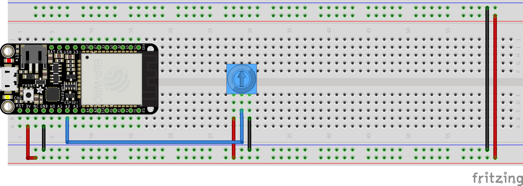
We will start by connecting a potentiometer to your ESP32. We'll use a breadboard with a plugged-in HUZZAH32 and connect a potentiometer to pin A2.
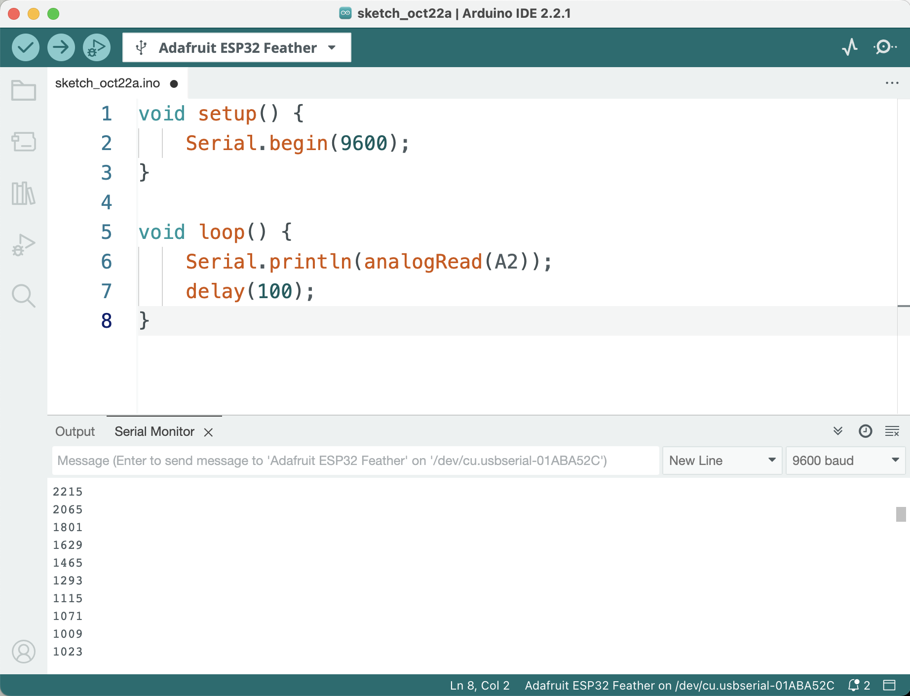
We will need initialize the serial connection in the setup() function with a specific baud rate - the rate of data transmission. It's not very important what that rate is as long as we are sending and recieving data on the same rate. Then we'll read the analog value coming from the A2 pin and send it off to the serial port on our computer via USB. We'll be using println() function because it will add a new line character after each printed statement, resulting in each print being on a separate line. We'll also a delay of 10 milliseconds to limit the number of prints to 100 times per seconds and avoid being overwhelemed by the flurry of information.
void setup() {
    Serial.begin(9600);
}

void loop() {
    Serial.println(analogRead(A2));
    delay(10);
}
Once you verify and upload this code to your ESP32 you should be able to open the Serail Monitor. Make sure the baud rate of your Serial Monitor matches the rate you specified in your code (9600 in our example) and you should be able to see the numbers change from 0 to 4095 as you move your potentiometer back and forth.
It might be important to point out that in the example we're only sending raw values, simply corresponging to the voltages read from the sensors. To make this data meaningful you might need to convert those values according to the specifications of your sensors.
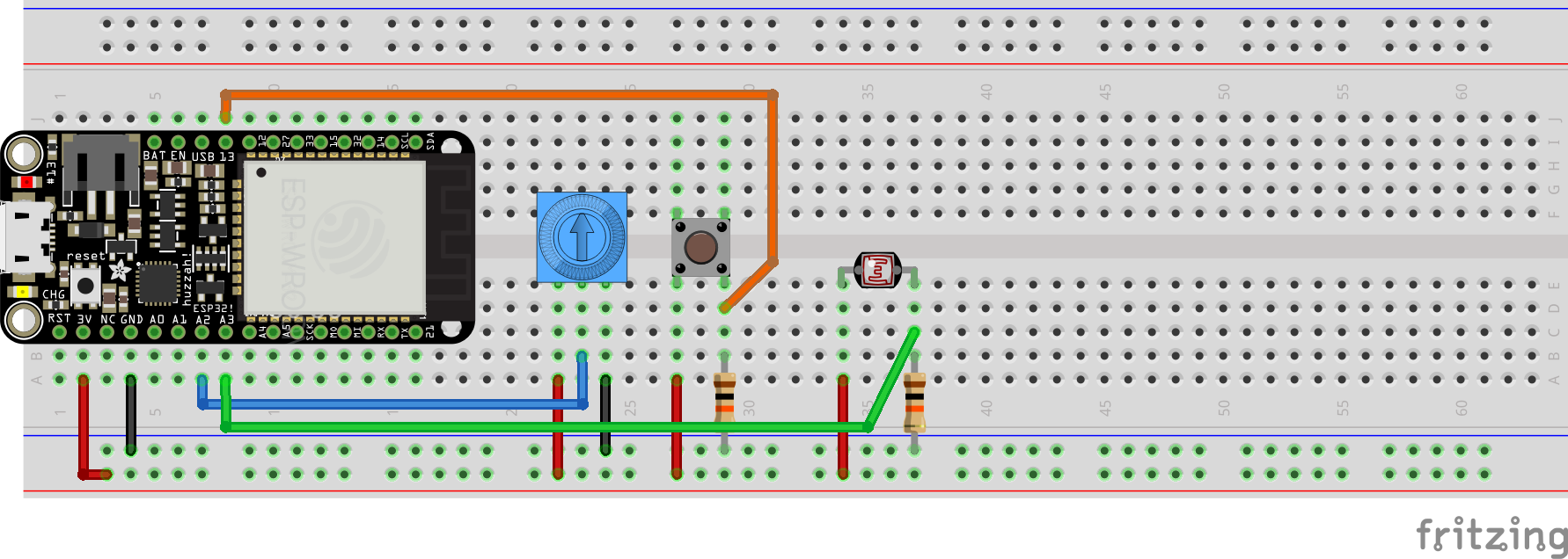
We can send multipe values from our microcontroller concurrently, provided we have a consistent encoding schema for them. So far we've sent one numerical value and use an end-of-line (aka new line) character ⮑ to identify the end of transmission - which would also allow us to separate one value from the next. This time we'll read from 3 sensors - a potentiometer, a button and a photoresistor - and send those 3 values at once. We'll use the following encoding: The position of the value will tell us which sensor it is from. The value in the first position will be from the potentiometer, the second - from the button, and the third - from the photoresistor. We'll separate those values with a predetermined character. It's not important which character that is, but a , is a convention, so we'll use that. Finally, we'll use end-of-line character to specify the end of transmission and the characters that come after it will count as the next reading of the three sensors.
The breadboard will be configured as follows:
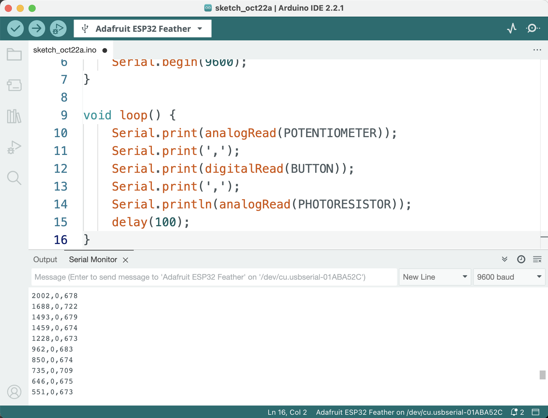
In our code we'll use print() functions to add values to a single transmission, but at the end of it we'll use println() to add the end-of-line character and signify the end of the current transmission and the beginning of the new one.
#define POTENTIOMETER A2
#define BUTTON 13
#define PHOTORESISTOR A3

void setup() {
    Serial.begin(9600);
}

void loop() {
    Serial.print(analogRead(POTENTIOMETER));
    Serial.print(',');
    Serial.print(digitalRead(BUTTON));
    Serial.print(',');
    Serial.println(analogRead(PHOTORESISTOR));
    delay(10);
}
This way we have 3 values trasnferred separated by a ','. We encode which sensor the value came from in the position of the value in the transmission, and encode the end of transmission with the character ⮑. If you open the Serial Monitor you should be able to see the corresponsing transmissions.
Since there is a very good chance that our electronics on the breadboard will not be shielded from interference, we might want to implement some form of filtering or averaging to smooth out the readings from the analog inputs (the digital ones are not really affected). The simplest approach that does not compromise performance is to rejeect any reading below a certain threshold. The value for this threshold will depend on the specific characteristics of your sensors and the environment in which they are operating. To implement this we need to keep track of both the current and the previous reding at any given point. Comparing the absolut value of the difference between the two readings to the threshold will help us reject any flucuations in the signal that are not intentional.
#define POTENTIOMETER A2
#define BUTTON 13
#define PHOTORESISTOR A3

int pPot = 0; // previous reading from the potentiometer
int cPot = 0; // current reading from the potentiometer
int pPhoto = 0; // previous reading from the photoresistor
int cPhoto = 0; // current reading from the photoresistor

int threshold = 100;

void setup() {
    Serial.begin(9600);
}

void loop() {
    cPot = analogRead(POTENTIOMETER);
    // if the difference between the current and previous reading is less than the threshold,
    //we reject the current reading and use the previous one instead
    if(abs(pPot - cPot) < threshold){
      cPot = pPot;
    }
    cPhoto = analogRead(PHOTORESISTOR);
    // if the difference between the current and previous reading is less than the threshold,
    // we reject the current reading and use the previous one instead
    if(abs(pPhoto - cPhoto) < threshold){
      cPhoto = pPhoto;
    }
    Serial.print(cPot);
    Serial.print(',');
    Serial.print(digitalRead(BUTTON));
    Serial.print(',');
    Serial.println(cPhoto);
    delay(10);
    // update the previous readings from the current ones for the next iteration
    pPot = cPot;
    pPhoto = cPhoto;
}